
![]()
This is an example of how the Cause Mapping® root cause analysis process can be applied to a specific incident. In this case the Buffalo Creek Flood of 1972 is captured as an example of the Cause Mapping investigation method. The three steps are 1) Define the problem, 2) Conduct the analysis and 3) Identify the best solutions. Each step will be discussed below.
Step 1. Define the Problem
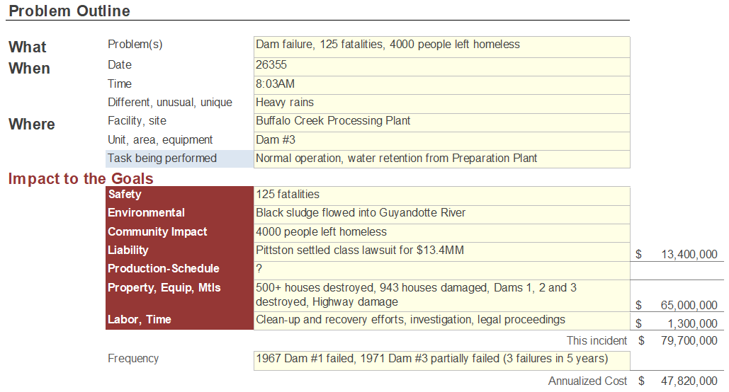
The first step of the Cause Mapping root cause analysis approach is to define the problem. First we ask four basic questions: What is the problem? When did it happen? Where did it happen? And how did it impact the goals?
In this case, the safety goal was impacted due to 125 fatalities. The environmental goal was impacted due to the sludge flow into the Guyandotte River, the outlet of the Buffalo Creek. The community was significantly impacted with over 4000 people left homeless. The parent company settled a class action lawsuit out of court for $13.4 MM, which impacted the liability goal. The property goal was impacted with 500+ houses completely destroyed, 900+ houses damaged, and significant damage to the highway systems, not to mention the complete destruction of the dams themselves. The labor goal was impacted due to the extensive resources required for clean-up and recovery efforts. The estimated total financial cost of the flood was ~$80 MM, however this does not adequately represent the long term devastation to the community and residents in the aftermath of the incident.
Step 2. Identify the Causes (The Analysis)
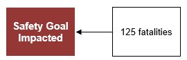
The analysis step is where the incident is broken down into causes which are captured on the Cause MapTM diagram. The Cause Map diagram starts by writing down the goals that were affected as defined in problem outline. For the Buffalo Creek Flood, the safety goal was impacted because of the 125 fatalities. This is the first cause-and-effect relationship in the analysis. Because of the magnitude of the impact to the safety goal, we will focus our discussion on the Cause Map diagram build from the safety goal.
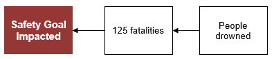
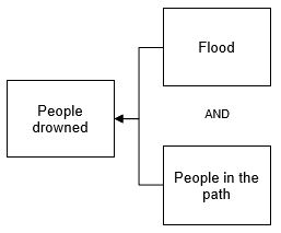
The analysis can continue by asking Why questions and moving to the right of either of the cause-and-effect relationships above. In this example we’ll start with the 125 fatalities which were a result of people drowning.
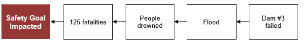
We continue to ask “Why” questions to develop the Cause Map diagram. People drowned due to the flood, which was caused by Dam #3 failing. Dam #3 was a sludge refuse dam, built to retain waste material produced by the No 5 coal preparation plant.
This is where the necessary and sufficient logic is applied to the Cause Map diagram. The flood is necessary to produce the effect of people drowning, but it is not, on its own, sufficient to produce the effect. The people being in the path of the flood waters is also required to produce that effect.
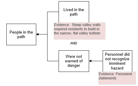
The people were in the path of the flood waters because they lived in the path and they were not warned of the danger. Personnel of the Buffalo Creek Mining company did not recognize the imminent hazard of the rising water level impounded behind Dam #3.
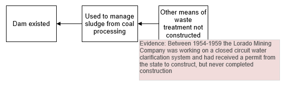
Any mechanical failure is a result of the stress on the object exceeding the strength of the object. Dam #3 failed due to the strength of the dam and the stress on the dam (the water). In addition, in order for a dam to fail, the dam has to exist.

In this case, the dam existed in order to manage the sludge waste produced at the coal preparation plant. This was a historical practice in the coal mining industry in order to reduce the costs of hauling away the unusable byproduct. In the late 1950’s the Lorado Mining Company, predecessor of the Buffalo Mining Company, had obtained a permit from the state to construct an alternate filter technology to process the sludge material, however the alternate process had never been constructed. This process would have eliminated the need for the refuse dam.
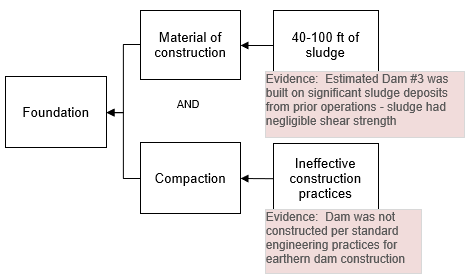
The strength of Dam #3 was a function of the material of construction and the foundation. The dam was constructed of coal refuse, a relatively low strength material, not typically used for earthen dam construction, but readily available at the location.
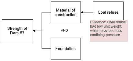
The foundation strength was a function of the material of construction and the compaction of the material. Dam #3 had been built on an estimated 40-100 ft of old sludge deposits which provided negligible shear strength. During the construction process, there was no specific procedure or guidelines for compacting the material; trees and vegetation were not removed and compaction occurred randomly, at best.
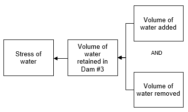
The stress on Dam #3 was due to the volume of water impounded behind the wall. It was estimated at the time of the incident there were 137 million gallons of water being contained. The volume of water is a function of both the water added and the water removed.
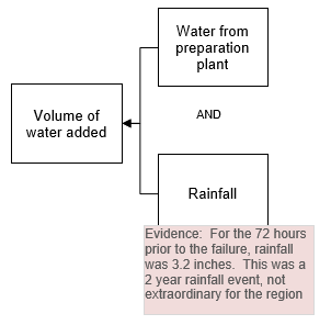
The water added to Dam #3 was from both the coal preparation plant, as well as recent heavy rainfall. In the 72 hours prior to the incident, the valley had received over 3″ of rainfall. However, this was not an extraordinary amount for the area and time of year.
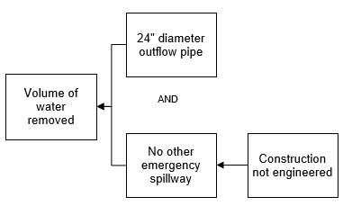
The water removed from Dam #3 was by design, a 24″ diameter outflow pipe located 7-8 ft below the top of the dam. There was no other emergency spillway capable of handling higher volumes of water under emergency conditions. This was another defect of a non-engineered dam.
Step 3. Select the Best Solutions (Reduce the Risk)
Once the Cause Map diagram is built to a sufficient level of detail with supporting evidence, it can be used to develop solutions. The Cause Map diagram is used to identify all the possible solutions for a given issue so that the best solutions can be selected. It is easier to identify many possible solutions from the detailed Cause Map diagram than an oversimplified high level analysis.
Solutions can be documented directly on the Cause Map diagram. Solutions are typically placed in a green box directly above the cause the solution controls. At this stage, all solutions are considered and put on the Cause Map diagram.
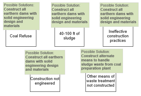
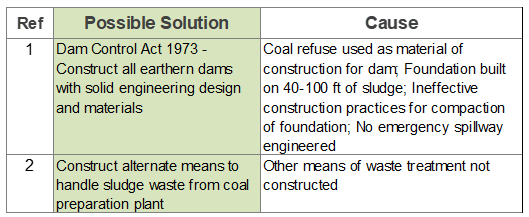
After the analysis is complete, the best solutions are selected based on the impacts to the organization’s goals. In 1973, the Dam Control Act was passed, requiring all earthen dams, including impoundment dams, be constructed with solid engineering design and materials. The enactment and enforcement of this law addressed many of the causes of the Buffalo Creek Flood. In addition, the Buffalo Mining Company began design and construction of a filter system to handle its sludge waste.
Cause Mapping® Root Cause Analysis Improves Problem Solving Skills
The Cause Mapping root cause analysis method focuses on the basics of the cause-and-effect principle so that it can be applied consistently to day-to-day issues as well as catastrophic, high risk issues. The steps of Cause Mapping root cause analysis are the same, but the level of detail is different. Focusing on the basics of the cause-and-effect principle make the Cause Mapping root cause analysis approach a simple and effective method for investigating safety, environmental, compliance, customer, production, equipment or service issues.
Click on “Download PDF” above to download a PDF showing the Root Cause Analysis Investigation.


