An effective root cause analysis digs into a problem to determine what caused it. But there are different levels of an analysis and each problem should be worked to the appropriate level of detail. An analysis can barely scratch the surface, or it can thoroughly dig into the details of an issue.
The digging is how the analysis gets more and more specific, but “specific” is a relative term. Details at one level can be too generic at a more detailed level. As an example, the loss of the Space Shuttle Challenger can be explained as a 4-Why Cause Map™ diagram shown below. This straight-line diagram reads left to right, one cause-and-effect relationship at a time. It starts on the left with an impact to safety because of the loss of seven crew members. Then as you move toward the right, you ask Why questions. The seven astronauts died because the Challenger broke apart when the external tank exploded which was caused by an O-ring failure.

This 4-Why analysis shows the loss of the Challenger was caused by an O-ring failure. This analysis is accurate, but there is more to it. By using photographs and video of the launch as well as telemetry data from the shuttle, investigators determined the O-ring failure allowed burning solid rocket fuel to leak from the side of the booster. The heat melted hardware that attached the booster to the tank. This caused the back portion of the booster to become disconnected—allowing it to swing into and rupture the already weakened external tank. Even though this specific chain of events is not shown in the 4-Why, if the O-ring would not have failed, the Challenger disaster would not have happened.
The O-ring is one specific component within the solid rocket booster. Considering the space shuttle had about 2.5 million parts, narrowing the investigation down to the O-rings in the field joint of the solid rocket booster is incredible detail. The O-ring failure may seem specific compared to the entire shuttle system, but it is too generic to prevent future O-ring failures. That one cause must be explained more thoroughly by breaking it into parts. This is a common mistake organizations and individuals make when investigating a problem. They look for the smoking gun; the one thing that caused the problem. It’s important to determine the O-rings are causally related to the issue, but it’s not the end of the investigation. Just the next spot to start digging. The O-ring failure on the Challenger can be broken into these two causes below.
O-Ring Failure Breaks Into Two Causes

You may be aware that it was below freezing at Cape Canaveral, Florida the morning of Jan. 28, 1986, which made it the coldest launch in NASA’s history. Because of the colder temperature, the O-ring material was less malleable. When compressed and released, the O-ring material moved slower, which allowed gases to flow through the gap. The cause-and-effect relationships above show how colder temperatures affected the seal of the O-ring.
More About the O-Ring
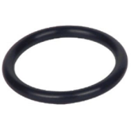
An O-ring is a ring of synthetic rubber with a circular cross section that when compressed in a groove provides a seal. They are used in many different sealing applications such as kitchen sinks, garden hoses, medical equipment, power plants and solid rocket boosters. The O-ring on the Challenger happened to be 12 feet in overall diameter.
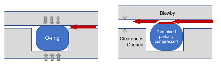
At launch, there is high pressure inside the solid rocket boosters as the igniters light the fuel. That pressure caused the pieces holding the O-ring to flex slightly. This relative movement between the two pieces (tang and clevis) reduced the compression on the O-rings. The diagram below shows how O-ring failure from the original 4-Why above can be broken into four different causes.
O-Ring Failure Breaks Into Four Causes

This flow of hot gasses across the O-ring is called blow-by, because the gas is blowing by the intended sealing surface. The flow of these hot gases, like a quickly moving stream, eroded the O-ring material. Instead of the O-ring making a dam, there is a high velocity flow of hot gases that cuts into the O-ring reducing its sealing capability even further.
The investigators, through a lot of digging, determined exactly what happened within the solid rocket boosters. Clear explanations are required to prevent problems from occurring in the future. The loss of compression on the O-rings is caused by the flexing of the joint, also called rotation, which is due to the design of the joint. And the loss of compression is cause by O-ring being less malleable in colder temperatures. Both causal paths shown below were required for the Challenger disaster to occur.
9-Why Cause Map™ Diagram with Two Causal Paths - Joint Design and Cold Temperature
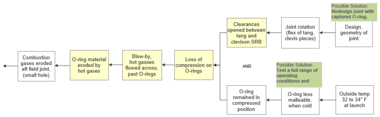
There were solutions down each path that together provided additional layers of protection to prevent this type of failure from occurring again. Two solutions are shown above in the green solution boxes.
One of the benefits of mapping the cause-and-effect relationships of a problem is that it allows everyone to see the same picture. If you know how to map the parts of your problems, adding detail doesn’t make the incident confusing—it makes it clearer. The details provide a complete explanation of what happened within an issue to find effective solutions. It’s something skilled troubleshooters and problems solvers do naturally, but anyone can learn it.
Interested in learning more about the lessons learned from the tragic loss of the Space Shuttle Challenger?