
On May 15, 2024, the National Transportation Safety Board (NTSB) released the preliminary report on its ongoing investigation into the Baltimore Bridge Collapse. This report brings clarity to many aspects of the incident and its impact that were unknown when we published our first blog on the accident. But as is often the case with large incidents, some mid-point investigation findings are hard to understand. We now know that the container ship Dali lost power before it struck the Francis Scott Key Bridge in Baltimore. How did it lose power? Well, that’s a bit confusing.
When we reach a point of confusion in our investigations, we often turn to diagrams. Diagrams allow us to visualize complex technical scenarios, making it easier to analyze and communicate what happened. In this blog, we’ll share the diagrams we created to understand the electrical issues onboard Dali, and, of course, an updated Cause Map™ diagram.
What We’ve Learned—and What Confused Us
When we started our analysis of the Baltimore Bridge Collapse back in March, we lacked a lot of information. We did not know if anyone was harmed or killed. We did not know if the containers onboard the Dali contained hazardous materials. We did not even know the exact time of the collision.
After reviewing the NTSB’s report, we updated our problem outline of the incident, shown below, with updated information in bold.
Updated Baltimore Bridge Collapse Problem Outline
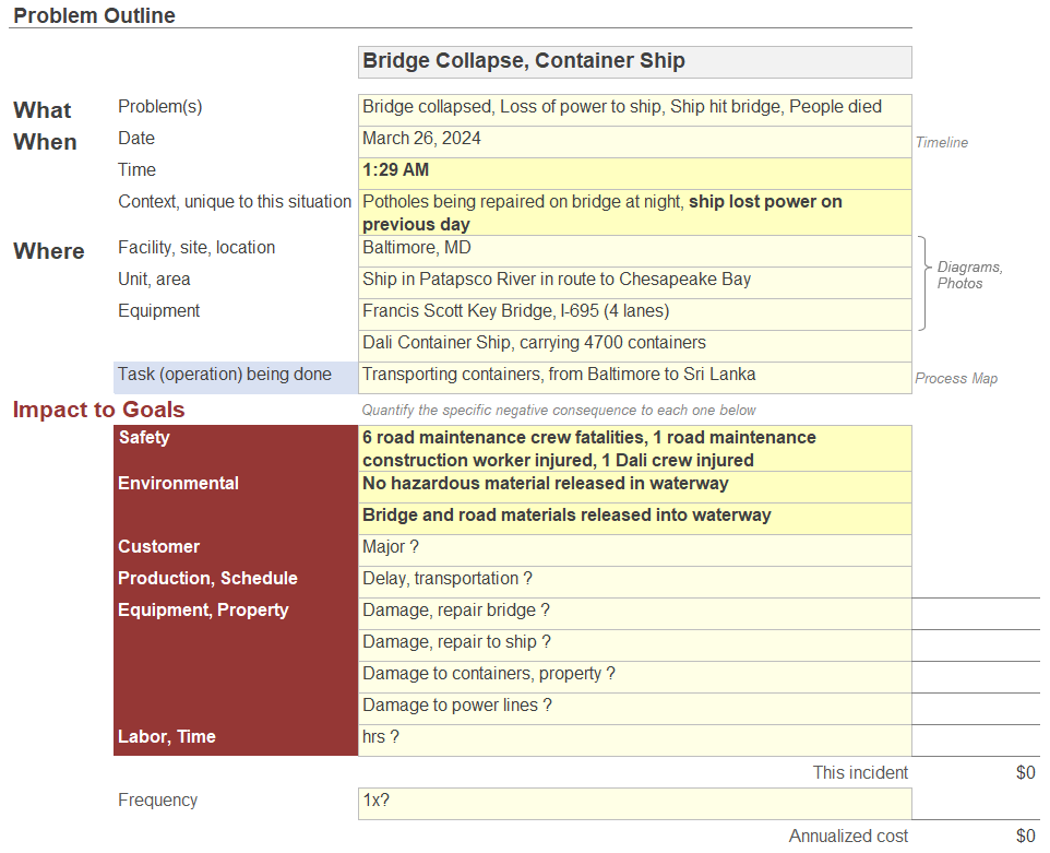
The NTSB’s report is preliminary, and many questions remain. However, one confirmed detail we found particularly interesting—and initially, confusing—was Dali’s initial power loss and the events that followed.
The Dali initially lost power on March 25, about 10 hours before it left port. The exhaust for the diesel engine driving the ship’s only online generator was blocked in, causing the engine to stall, which caused the engine to trip. The crew had to manually close circuit breakers. After they did, another diesel generator tripped on low fuel pressure, causing a second blackout in port. The ship departed, then lost power twice again in the moments before it hit the bridge. These power issues are very interesting, but it’s important to note that we currently do not know whether they are correlated or causally related to the incident.
The NTSB report has a lot of information about the sequence of electrical changes onboard the Dali, but because these details are technical and flow through multiple sections of the report, it’s not easy to understand exactly what happened. Diagrams to the rescue!
Visualizing the Sequence of Electrical Configurations After Dali’s Departure from Port
Before we jump in, two caveats: One, we created the following diagrams based on our interpretation of the NTSB’s preliminary report, which is preliminary and thus subject to change. Two, not every investigation or investigator needs diagrams, but for me to understand this incident, it was essential to visualize the sequence of events with incident diagrams.
Dali Electrical Configuration—Leaving Port
 click the image to enlarge
Following the second in-port blackout, the crew switched the bus configuration to use breakers HR1 and LR1 and the TR1 transformer. On the previous voyage the Dali was operating normally through HR2, TR2 and LR2. At 12:45 AM, the Dali departed Baltimore’s Seagirt Marine Terminal with its electrical equipment under the configuration above.
Dali Electrical Configuration—Circuit Breakers Unexpectedly Open
 click the image to enlarge
At 1:25 AM, circuit breakers HR1 and LR1 unexpectedly opened, causing the low voltage bus to lose power. Low voltage equipment, including water cooling and oil pumps to the main engine, tripped. As the main 55,626 hp engine requires all the support equipment, when the support equipment trips, the main engine trips. Then, the emergency generator was introduced into the emergency bus, which powered only emergency equipment.
Dali Electrical Configuration—Emergency Generator Turns On
 click the image to enlarge
Shortly after 1:25 AM, the emergency generator turned on and the breaker closed to power some of the low voltage bus at reduced capacity. The ship’s rudder turn capability was restored, but only through pump 3, which makes the rudder turn more slowly and is less effective without the propeller moving. (Note that the configuration of the emergency generator in our diagram follows the description provided in the text of the NTSB report and differs from the simplified electrical configuration diagram presented in the report [Figure 5]).
Dali Electrical Configuration—Circuits Manually Closed
 click the image to enlarge
After the emergency generator turned on, the crew manually closed circuits HR1 and LR1 to bring the high and low voltage bus to full capacity to try and recover power to the entire ship.
Dali Electrical Configuration—Circuit Breakers Trip Open
 click the image to enlarge
Following the restoration of the low-voltage bus, the DGR3 and DGR4 circuit breakers—which connect diesel generators 3 and 4 to the high-voltage bus—tripped open. This caused complete power failure to both the high voltage system and the low voltage system. Circuits LR1 and LR2 also tripped open.
Dali Electrical Configuration—Power Restored to High Voltage Bus
 click the image to enlarge
After the power failure, diesel generator 2 was introduced into the high-voltage bus to restore normalcy to it. Circuit breaker DGR2 was closed, and power was restored to the high-voltage bus.
Dali Electrical Configuration—Full Electrical Power Restored
 click the image to enlarge
The crew then closed circuit breakers HR2 and LR2, restoring full electrical power to the high voltage bus and low voltage bus—just before the Dali hit the Francis Scott Key Bridge.
I can only imagine the chaos on board as the crew tried to get the ship’s power restored. Only four minutes elapsed between Dali’s first loss of power and its collision with the bridge. It took me way longer than 4 minutes to understand the power issues, and I didn’t have the stress of trying not to hit a bridge.
The Dali lost control while it was in the ship channel which caused it to hit the Key Bridge. We now understand the cause-and-effect relationships from the electrical issues to the loss of control, but what we’re missing is the causes of the electrical issues.
The Investigation Continues
We’ve updated our Cause Map diagram for the Baltimore Bridge Collapse to show how the Dali lost control. The power loss is included, but we do not yet know the causes of the circuit breaker failures. We will update our Cause Map diagram further when the NTSB completes its investigation.

click the image to enlarge
Stay tuned for our complete Cause Map diagram on this incident. And if you guessed that all I used to create these diagrams was Excel, you’re right! Working with shapes in Excel takes some practice, but once you get the hang of it, you can diagram anything you want. Get started with the tips I shared in How to Create Good-Looking Cause Map™ Diagrams.

Editor’s Note: This blog is the second part of a two-part series. View Part 1.


